CEMA guidelines for underground conveyor belt support
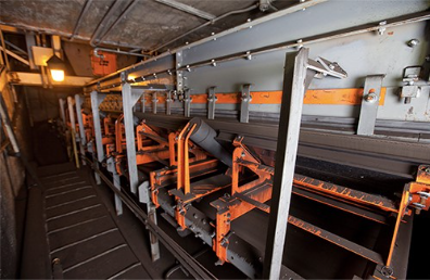
To control dust and spillage in underground environments, the design engineer must do whatever is practical to keep the belt’s line of travel consistent. Another concern is space allowances for maintenance, as one side of the conveyor may be too close to the wall to access. While many factors influence the belt’s running line inside and outside the loading zone, proper support and design for safety are key.
Modern belt support systems are designed to maintain a smooth belt path with minimal bumping or disruption to settled cargo, avoiding gaps in the loading zone and minimizing belt sag along the system’s length. New designs reduce maintenance costs and improve safety by providing easier access to components and reducing the labour required for routine maintenance.
Building proper belt support
Before installing supports, precisely align the stringer, preferably using laser surveying. Follow the Conveyor Equipment Manufacturers Association’s (CEMA) Appendix D tolerances, secure rigid footings and account for loads and impacts to prevent excessive belt deflection.
As noted in Martin Engineering’s “Foundations” industry reference book, the belt’s line of travel must be stabilized with proper support in the loading zone to achieve an effective, minimum-spillage conveyor. With a true belt line, support components can better maintain a sealed environment. According to CEMA, there are several techniques and components that control belt sag by improving belt support in the loading zone. They include idlers, belt support cradles and impact cradles.
Idler type and rating
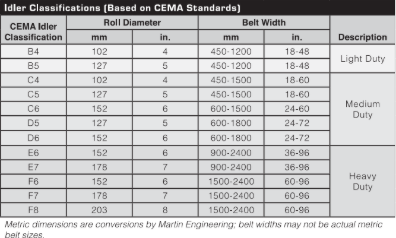
Idlers shape and support the belt and cargo, while minimizing the power needed to transport the materials. They are classified by roller diameter, service type, operating condition, belt load and belt speed, and then rated for load-carrying capacity and calculated bearing life. CEMA uses a two-character code that indicates the idler classification and implied load rating, with a letter code followed by the idler diameter in inches, resulting in classes from B4 to F8.
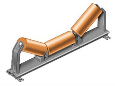
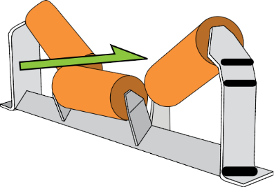
Troughed carrying idlers typically consist of three rolls — one horizontal roll in the centre with inclined (or wing) rolls on either side. These support and shape the belt into a specific trough angle for the conveyance of cargo.
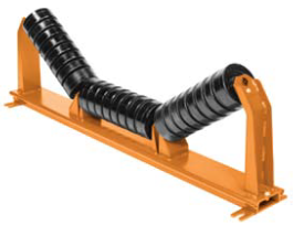
Impact idlers typically have a similar load rating to standard idlers, with the same shafts and bearings. One disadvantage is that each idler supports the belt only at the top of the roller, so the rounded shape and deflective rubber will allow the belt to oscillate or sag away slightly from the ideal flat profile.
Picking idlers have a shallow trough with a wide base, giving larger raw material a wider area on which to settle. Without that wide base, large chunks would drift to one side of the belt or the other, causing misalignment.
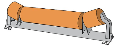
Offset idlers place the center roller slightly in front of the wing rollers. By reducing the overall height of the idler set, this configuration is well-suited to cramped spaces, such as mines that require heavy-duty support but lack space.
Belt sag
Belt sag, when viewed from the side of the transfer point, is the vertical deflection of the belt from a straight line across the top of the two adjacent idlers. Even a millimeter of sag is enough to permit fines to become entrapped, leading to abrasive wear. The result is typically high-temperature friction and belt damage, requiring unscheduled downtime to fix.

Idler spacing and power consumption
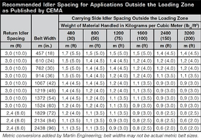
Sagging causes the load to shift as it is carried up and over each idler and down into the valley between, increasing belt wear and power consumption while contributing to fugitive dust and spillage. CEMA has produced tables of recommended idler spacing for applications outside the loading zone.
Idler maintenance
When idlers seize or sustain damage, the unprotected underside of the belt can be damaged as well. Extreme temperatures from the friction may cause combustible cargo or the belt to ignite, carrying the fire the entire length of the belt within seconds.
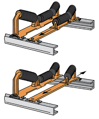
In the past, an idler set could be difficult to access and change, often requiring the worker to reach in past the belt plane. To address this issue, track-mounted idlers are designed as an in-line set on the same track assembly, engineered to be easily extracted in separate sections for maintenance outside of the conveyor plane. This enables faster, easier maintenance in a safe environment, reducing labor and downtime.
Impact cradles in the loading zone
Impact cradles continuously support the belt edge, eliminating belt sag between the idlers. Some bulk-handling operations drop material from a great height. Repeated high magnitude impacts without proper support can damage the belt. An example would be a 0.46-metre lump of sandstone dropping 2.13 metre. This lump will hit the belt with the same energy as a fully loaded refrigerator falling 3.05 metre.
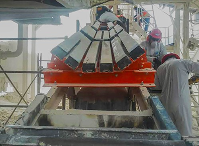
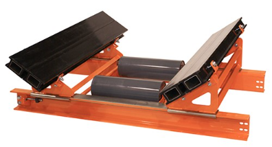
To minimize these negative effects, impact cradles are constructed of a steel support framework with individual impact-absorbing bars made from durable elastomeric materials that combine a slick top surface with one or more sponge-like secondary layers. Some models allow the bumpers to be flipped to double the service life.
Support cradles
Instead of using rolling idlers following the impact cradle, support cradles use low-friction bars to support the belt profile. Support cradles perform two functions: controlling belt sag in the load zone to reduce spillage and providing a slick surface on which the belt can ride. Other benefits of using cradles under the transfer point include fewer moving parts and no lubrication required.
Cradle maintenance
Some cradles slide away from the stringer, allowing one worker, using one tool, to perform safer maintenance outside the belt plane, reducing labour and downtime.
R. Todd Swinderman is president emeritus of Martin Engineering.
Comments