Reducing hidden electrical risks in mining operations
Practical considerations for grounding and braking systems
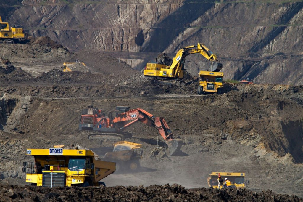
Mining operations subject electrical infrastructure to extreme punishment. Subterranean moisture, abrasive mineral dust and relentless mechanical vibration degrade equipment continuously. Electrical failures in these settings cause severe safety hazards and trigger catastrophic production halts. Protecting this critical infrastructure requires flawless system design and rigorous component specification.
Engineers must focus heavily on the specific components responsible for managing excess energy and fault currents. Neutral grounding systems and dynamic braking resistors form the primary defence layer for expensive mine machinery. These passive safety devices sit quietly in the background during normal operations. They activate only during dynamic shifts or critical fault conditions to absorb massive amounts of destructive energy. Understanding how to properly specify and maintain these systems ensures total operational reliability and protects personnel from severe electrical hazards.
The mechanics of ground faults in mining environments
Ground faults represent the most frequent electrical anomaly in heavy industrial settings. An active mine features miles of trailing cables powering mobile substations, massive draglines and continuous miners. Insulation degradation happens rapidly owing to constant physical wear, rockfalls and water ingress. When insulation fails on an unprotected, solid-grounded system, massive destructive currents flow directly through the equipment casing to the earth.
This uncontrolled flow of energy generates extreme thermal and magnetic stress. The resulting fault current destroys motor windings, melts expensive switchgear and creates severe arc flash hazards for any nearby personnel. Uncontrolled ground faults completely vaporize copper conductors and ignite surrounding combustible materials.
To mitigate this destructive force, engineers implement resistance grounding networks. Placing a specifically rated resistor between the system neutral point and the earth ground limits the fault current to a safe, highly predictable level. This controlled approach protects the physical infrastructure from thermal damage and provides protective relays with enough time to isolate the faulted circuit safely.
Implementing high and low resistance grounding strategies
Mining engineers typically deploy two distinct grounding strategies based on the voltage and operational requirements of the specific circuit. High resistance grounding restricts the fault current to a very low threshold, typically under 10 amps. This extreme limitation allows the electrical system to continue operating safely even with an active single-phase ground fault. Maintenance personnel gain valuable time to locate and isolate the issue systematically without halting production on a critical processing line.
Low resistance grounding manages higher voltage distribution networks and medium-voltage motor circuits. This configuration permits a larger, controlled current flow, often ranging from 100 to 400 amps. This specific current level is designed to trigger protective relays immediately. The relays sense the fault and trip the upstream circuit breaker instantly. This rapid isolation prevents extensive damage to the high-voltage distribution infrastructure and clears the hazardous condition from the mine grid. Both strategies rely entirely on the mechanical and thermal integrity of the neutral grounding resistor.
Specifying robust grounding hardware for harsh conditions
Specifying a neutral grounding resistor requires a deep understanding of the environmental stressors present in mining operations. Standard commercial components degrade quickly when exposed to corrosive atmospheres, airborne mineral dust and continuous mechanical vibration. Without proper enclosure design and material selection, these conditions can lead to insulation breakdown and dangerous electrical flashovers during a fault event.
Engineering teams typically evaluate grounding hardware based on thermal capacity, mechanical durability and environmental protection ratings. Specialized manufacturers design resistor systems specifically for heavy industrial applications, where equipment must withstand repeated thermal cycling and structural stress. In these environments, reinforced resistor elements and sealed enclosures help maintain electrical integrity under fault conditions.
The focus, often defined during the discovery phase of a project, should remain on performance under worst-case scenarios. During a ground fault, the resistor must absorb and dissipate energy without structural deformation or loss of resistance value. Selecting hardware that is engineered for high heat loads, vibration resistance and contamination control ensures the grounding system performs reliably when it is needed most.
The physics of dynamic braking in heavy haulage
Mining operations move millions of tonnes of raw material using massive electric motors. Downhill overland conveyors, deep shaft hoists and electric haul trucks generate enormous amounts of kinetic energy during deceleration. Variable frequency drives control these massive motors efficiently during standard forward operation. During deceleration or downhill braking, the mechanical load overhauls the motor. The motor then acts as a generator, pumping massive amounts of electrical power back into the drive’s direct current bus.
The drive system must dissipate this regenerative energy safely to prevent damaging overvoltage conditions from destroying the sensitive power electronics. Dynamic braking resistors absorb this excess electrical energy and convert it entirely into ambient heat. This rapid thermal conversion protects the drive electronics and allows the heavy machinery to stop precisely and safely under massive loads. The braking resistor acts as the ultimate mechanical fail-safe, ensuring multi-tonne hoists and fully loaded conveyors maintain perfect speed control on steep gradients.
Critical variables in braking resistor selection
Selecting the correct braking resistor demands precise thermal and mechanical calculations from the engineering team. A common engineering oversight involves severely underestimating the duty cycle of the application. Conveyors operating on long, steep declines require continuous energy dissipation for extended durations. Specifying a resistor rated only for intermittent duty causes rapid overheating and catastrophic element meltdown.
Engineers must calculate the peak power required to stop the load, the continuous power rating for sustained braking, and the exact ohmic value required by the variable frequency drive. The physical installation space also dictates the cooling requirements. Underground electrical rooms suffer from highly restricted airflow, compounding the thermal management challenge. Designers must implement forced-air cooling fans or specify significantly oversized natural convection units to handle the environmental heat load. Furthermore, the mechanical design of the resistor bank must withstand the constant vibrations transmitted by the heavy machinery it protects. Utilizing thick grid-style elements with robust ceramic insulators prevents mechanical fatigue and electrical shorting over years of continuous operation.
Maintenance and lifecycle monitoring protocols
Even the most robust electrical components require proactive monitoring. Grounding and braking systems possess a passive operational nature, meaning they only heat up during specific events. This intermittent usage easily masks developing issues from the maintenance team. Teams must implement routine testing protocols and use maintenance management software to verify the electrical and physical integrity of the resistor banks. Inspecting for element oxidation, checking insulator cleanliness and verifying the torque on all terminal connections prevent unexpected failures.
Implementing modern continuous monitoring relays adds a critical layer of visibility to these passive systems. Digital relays constantly measure the resistor’s continuity, leakage current and thermal state. Integrating these smart sensors directly into the mine’s central control system provides operators with real-time alerts. For teams that need a more tailored way to collect inspection data, monitor equipment status and manage maintenance actions, SolveIt mobile consultants can help turn field data into structured operational workflows. Catching a loose connection or a compromised insulator early prevents a minor degradation from escalating into a complete system failure during a critical braking event.
Conclusion
Operational reliability in the mining sector depends entirely on managing extreme physical and electrical forces. Uncontrolled ground faults and massive regenerative kinetic energy possess the capacity to destroy millions of dollars of infrastructure instantly. Implementing robust neutral grounding systems and precisely specified dynamic braking resistors neutralizes these hidden threats completely. Engineering teams protect their personnel and secure their daily production targets by demanding premium, heavy-duty components tailored exactly to the harsh realities of the mine.
MegaResistors specializes in the design, manufacturing and application of power resistors.
Related Posts

TNM reveals latest bonus prize Treasure Hunt clue
September 30, 2026
TNM reveals latest bonus prize Treasure Hunt clue
Gold refining goes electric
September 30, 2026
Gold refining goes electric
Montage pours first gold at Koné ahead of schedule
September 29, 2026
Montage pours first gold at Koné ahead of schedule
Mining Forum: Miners have cash but lack the crews
September 29, 2026
Mining Forum: Miners have cash but lack the crews
Troilus nails down US$850 million for gold-copper mine redevelopment
September 28, 2026
Comments